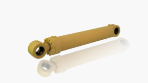
For heavy equipment operators and procurement managers, the hydraulic cylinder is the muscle of the machine. Whether lifting a 40-ton mining truck bed or actuating the arm of an excavator, these components convert fluid power into linear mechanical force.
Understanding the internal mechanics of hydraulic cylinders is not just academic—it is essential for troubleshooting failures, optimizing maintenance schedules, and selecting the correct specifications for severe-duty applications. This guide breaks down the operational physics, component anatomy, and failure points of hydraulic actuators from a professional engineering perspective.
What is a Hydraulic Cylinder?
A hydraulic cylinder is a linear actuator used to apply unidirectional force through a unidirectional stroke. It functions by transferring energy from a pressurized fluid (typically oil) into a movable piston rod.
Technically, it operates on Pascal’s Law, which states that pressure applied to a confined fluid is transmitted undiminished in every direction. In a cylinder, this pressure acts upon the piston area to generate force.
The Fundamental Equation:
$$Force = Pressure \times Area$$
- Pressure: The hydraulic system pressure (measured in PSI or Bar).
- Area: The surface area of the piston (for extension) or the annulus area (for retraction).
Anatomy of a Heavy-Duty Cylinder
A cylinder is more than a steel tube. It is a precision pressure vessel. Understanding its sub-components is critical when sourcing parts or vetting hydraulic cylinder manufacturers.
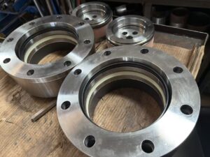
1. The Barrel (Cylinder Tube)
The barrel acts as the pressure containment vessel. It is typically machined from seamless steel tubes (such as St52 or honed DOM tubing). The internal surface finish is critical; it must be honed to a specific roughness (Ra value) to hold a microscopic oil film that lubricates the seals.
2. The Piston and Rod
The piston separates the cylinder into two pressure chambers: the cap end (bottom) and the rod end (head).
- Hydraulic cylinder pistons: Usually machined from steel or ductile iron, these carry the main seals and guide rings.
- The Rod: This transmits the force to the load. In mining, rods are often induction hardened and chrome-plated to resist impact and corrosion.
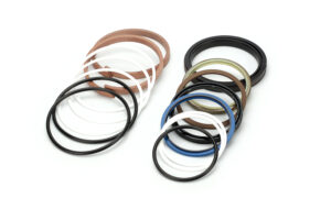
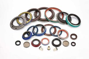
3. The Sealing System
This is the most frequent point of failure. A standard seal kit includes:
- Piston Seals: Prevent oil bypassing between chambers (internal leakage).
- Rod Seals: Prevent oil leaking out of the cylinder (external leakage).
- Wiper/Scraper: Cleans the rod as it retracts to prevent dirt ingress.
Note on Environmental Specs: Standard NBR seals fail in extreme climates. For operations in Russia or Canada, procurement must specify a low-temperature hydraulic cylinder seals kit -50°C. These use specialized polyurethane compounds that remain flexible in sub-zero conditions, preventing immediate seal fracture upon startup.
How It Works: The Operational Cycle
Most heavy machinery uses double-acting cylinders. Here is the step-by-step fluid dynamic process.
Extension Stroke (Pushing)
- Hydraulic fluid is pumped into the Cap End port.
- Fluid pressure acts against the full surface area of the piston.
- Fluid on the Rod End is forced out through the return line to the tank.
- Because the pressure acts on the full piston face, extension generates the maximum force of the cylinder.
Retraction Stroke (Pulling)
- Fluid is pumped into the Rod End port.
- Pressure acts only on the “annulus area” (the piston surface area minus the rod cross-sectional area).
- Because the effective area is smaller, retraction generates less force but generally moves at a higher speed (as the volume to fill is smaller).
Special Case: Telescopic Cylinders
For applications requiring a long stroke from a compact retracted length (like dump trucks), a double acting telescopic cylinder is used. These feature nested stages (sleeves) that extend sequentially. They require complex engineering because the effective area—and therefore the force capability—decreases with each stage that extends.
Maintenance and Failure Analysis
Understanding how a cylinder works allows you to diagnose why it fails. Hydraulic cylinder repair is often a result of preventable contamination or overloading.
| Failure Mode | Visual Indicator | Root Cause |
| Rod Scoring | Deep vertical scratches on the chrome rod. | Contaminated oil or abrasive dust ingress due to failed wiper seals. |
| Ballooning | The barrel bulges outward. | Over-pressurization beyond the yield strength of the steel tube. |
| Drifting | The load drops slowly when the valve is closed. | Internal hydraulic cylinder piston seal bypass (leakage from cap to rod side). |
| Diesel Effect | Burn marks or blackening on seals. | Air trapped in the oil compresses and ignites, burning the seals. |
The “Repair vs. Replace” Decision
When a critical cylinder fails, lead time is the enemy.
- OEM Replacement: Often carries a 12+ week lead time.
- Repair: Feasible if the barrel is not scored.
- Fast Manufacturing: For unrepairable units where OEM lead times are unacceptable, sourcing a custom hydraulic cylinder manufacturer fast delivery service (often <2 weeks) is a strategic necessity for mining sites to minimize downtime costs.
Common Misconceptions
Myth 1: Larger Rods Mean More Force
Fact: A larger rod actually reduces the retraction force because it reduces the annulus area on the rod side. A larger rod increases column strength (resistance to buckling) but does not increase push force.
Myth 2: 100% Seal Efficiency is Possible
Fact: All dynamic seals rely on a microscopic film of oil for lubrication. While external leakage should be zero, a minute amount of fluid transfer is physically necessary for seal longevity. However, visible dripping is a failure.
Myth 3: Pressure equals Speed
Fact: Pressure determines Force. Flow rate (Gallons Per Minute or LPM) determines Speed. Increasing pressure will not make the cylinder move faster; it will only allow it to lift a heavier load.
FAQ: Technical Summaries for Decision Makers
What is the difference between single and double acting cylinders?
A single-acting cylinder uses hydraulic pressure to extend, but relies on gravity or an external spring to retract (e.g., a simple bottle jack). A double-acting cylinder uses hydraulic power for both extension and retraction, providing control in both directions (e.g., an excavator arm).
How do I calculate the force of a hydraulic cylinder?
Multiply the system pressure by the piston area.
Formula: $Force (lbs) = Pressure (psi) \times (\pi \times r^2)$.
Note: Ensure you use the radius of the piston, not the rod.
Why do hydraulic cylinders drift?
Cylinder drift occurs when oil leaks internally across the piston seal from the high-pressure side to the low-pressure side, or when the control valve spool leaks. To isolate the cylinder, cap the ports; if it still drifts under load, the piston seal is the culprit.
Can I use a standard cylinder for side-load applications?
No. Standard cylinders are designed for linear push/pull forces. Side loads (radial forces) will accelerate wear on the guide bands and rod seals, eventually bending the rod. Applications with side loads require spherical bearings or trunnion mounts.
System Checklist for Buyers
Before commissioning or purchasing hydraulic cylinders, verify the following:
- [ ] Port Orientation: Are ports accessible for hose routing in the machine’s mounted position?
- [ ] Cushioning: Does the application require internal cushions at the end of the stroke to prevent metal-on-metal impact?
- [ ] Buckling Load: Has the rod diameter been calculated against the stroke length to prevent buckling at full extension?
- [ ] Seal Compatibility: Are the hydraulic cylinder seals compatible with the specific hydraulic fluid (e.g., mineral oil vs. fire-resistant water-glycol)?
- [ ] Chroming Spec: For mining, does the rod plating meet ASTM B117 salt spray test requirements (typically 500+ hours)?