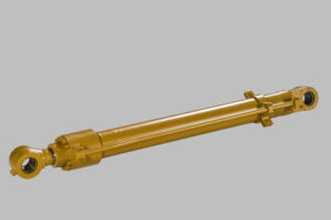
Sourcing a replacement hydraulic cylinder when the original OEM part number is unreadable, missing, or simply not findable in any catalog is a problem that lands on aftermarket procurement desks weekly. The cylinder works. The cylinder failed. The cylinder needs to be replaced. But the only way to specify the replacement correctly is to measure what the existing cylinder actually is.
That measurement process — taking the four critical dimensions that identify a cylinder uniquely — is straightforward field work. With the right tools and a methodical approach, anyone with basic mechanical skills can produce dimensional data accurate enough to cross-reference against an aftermarket manufacturer’s catalog and order a correct replacement. Without the right tools or with sloppy technique, the measurements produce a cylinder that physically fits but performs incorrectly, leaks, or fails prematurely.
This hydraulic cylinder measurement guide walks through the practical field procedure for taking bore, rod, and stroke measurements on an existing cylinder, what tools actually work, where the measurement errors hide, and how to convert the field data into a clean specification for aftermarket sourcing. It applies to excavator hydraulic cylinder replacement, loader cylinder identification, dump truck cylinder cross-referencing, and any heavy equipment cylinder that needs to be specified from the part itself rather than from a parts book.
The Four Measurements That Define a Cylinder
A hydraulic cylinder is identified by four dimensional parameters. Get these four right and the replacement is sourceable. Get one wrong and the wrong part arrives at the workbench.
Bore diameter (D). The inside diameter of the cylinder barrel, measured across the bore where the piston operates. Determines extension force at any given pressure and sets the geometry the piston seal must accommodate. Typical heavy equipment bores run 60 mm to 300 mm depending on the cylinder class.
Rod diameter (d). The outside diameter of the piston rod measured at the exposed rod surface. Determines retraction force and column buckling capacity. Heavy equipment rods run 40 mm to 200 mm.
Stroke length (L). The travel distance from fully retracted to fully extended position. Determines the geometric range of motion the cylinder provides. Heavy equipment strokes typically span 600 mm to 3,000 mm; mining-class cylinders extend to 8,000 mm or more.
Mounting and end-fitting dimensions. Pin diameters at the rod end and base end, pin-to-pin distance at full retraction, port location and thread specifications, and any flange or trunnion mounting interfaces. These are the dimensions that determine whether the cylinder will physically fit and connect to the machine.
These four sets of measurements — bore, rod, stroke, and mounting — uniquely specify a hydraulic cylinder for replacement purposes. The OEM part number is essentially shorthand for these dimensions plus material specifications. When the part number isn’t available, the measurements substitute for it.
Tools You Actually Need
The tool selection determines measurement quality more than operator skill on most jobs. Adequate tools take ten minutes to learn and produce accurate results; inadequate tools produce ranges of measurements with no clear “right answer,” which leads to procurement errors downstream.
For Bore Diameter
Dial bore gauge with appropriate range. The professional standard for bore measurement. Measures to 0.01 mm (0.0004″) resolution. The gauge head includes interchangeable extensions to cover different bore size ranges, with telflon contact buttons that won’t damage the bore surface. Setting the gauge against a calibrated outside micrometer at the nominal bore size establishes the zero reference; the gauge then reads variation from that reference.
Inside micrometer (rod-style or three-point). Three-point inside micrometers (tri-mics) provide direct reading at the contact point without secondary measurement. Suitable for bore sizes from approximately 40 mm to 300 mm. Less prone to operator alignment error than two-point gauges, but show only an average diameter at the measurement location — they won’t reveal out-of-round conditions.
Telescoping bore gauge (snap gauge) with outside micrometer. Lower-cost option suitable for field work where dial bore gauges aren’t available. The T-shaped telescoping gauge expands into the bore, gets locked at contact, then is removed and measured with an outside micrometer. Accuracy depends heavily on operator technique — proper feel for contact pressure separates good measurements from misreadings of 0.05–0.10 mm.
What doesn’t work for cylinder bores: Standard caliper jaws are designed for shallow measurement (typically 10–15 mm jaw depth) and cannot reach into a cylinder bore far enough to provide a useful measurement. Anyone trying to measure cylinder bore with calipers is producing a guess, not a measurement.
For Rod Diameter
Outside micrometer. The standard tool. Resolution to 0.01 mm or 0.001″. Measures across the rod’s outside diameter at the contact point. Easy to use correctly; requires only that the operator squeezes the thimble to consistent contact pressure (avoiding over-tightening that compresses the rod surface slightly).
Digital caliper. Acceptable for field rod measurement when micrometer isn’t available. Resolution typically 0.01 mm or 0.001″. Lower accuracy than a micrometer (typically ±0.02 mm versus ±0.005 mm) but sufficient for cross-referencing against standard rod size catalogs. The key is using the inside caliper jaws or the outside jaws consistently — mixing them produces measurement scatter.
For Stroke Length
Steel measuring tape, 5–10 meter range. Measure the exposed rod length with the cylinder at full retraction, then with the cylinder at full extension. The difference is the stroke. A 3 mm or 5 mm tape graduation is sufficient — stroke length tolerance is typically wider than the bore tolerance.
For cylinders that can’t be cycled (e.g., the cylinder is removed from the machine and pressure isn’t available), measure the rod-end to barrel-end distance with the cylinder fully collapsed, then mark a chalk reference on the rod and pull it manually to full extension to capture the stroke directly.
Reference Tools
Calibrated reference standards (gauge blocks, ring gauges). Required for periodic calibration of micrometers and dial bore gauges. Field measurement work can use micrometers calibrated within the past 12 months. Critical accuracy work — production manufacturing or QC verification — requires more frequent calibration.
How to Measure Bore Diameter on a Cylinder
The bore measurement is the most critical and the most likely to be mis-done. Procedure that actually produces useful data:
Preparation:
- Disassemble the cylinder if it isn’t already. Bore measurement requires access to the inside of the barrel.
- Clean the bore thoroughly. Hydraulic oil residue, contamination, or material from worn seals will interfere with the gauge contact and produce noisy measurements.
- Inspect the bore visually. Note any obvious scoring, pitting, or barrel deformation. Damage areas should be measured separately to assess wear, but baseline measurements should be taken in areas that appear undamaged.
Measurement at multiple positions: 4. Take measurements at the top, middle, and bottom of the bore (three Z positions along the length). Measure each position in two perpendicular directions (typically referred to as X and Y axes). This produces six measurements per bore. 5. For mid-range and large bore cylinders, add additional Z positions if the bore length is long. Six to nine positions distributed along the length is the standard professional practice.
Setting the gauge: 6. Set the dial bore gauge against a calibrated outside micrometer at the nominal expected bore size. Most heavy equipment cylinders use standard bore sizes — 80, 90, 100, 110, 120, 130, 140, 160, 180, 200 mm and so on. Set the gauge against the closest standard size first, then refine based on initial readings. 7. Verify the zero by rocking the gauge in the setting fixture. The minimum reading on the dial is the true zero reference.
Taking the measurement: 8. Insert the gauge head into the bore at the first measurement position. Hold the gauge with the centering shoes contacting both walls of the bore. 9. Rock the gauge slightly forward and back. The smallest reading (the point where the gauge head is exactly perpendicular to the bore axis) is the correct measurement at that position. 10. Record the reading. Move to the next position. Repeat.
Interpreting results:
Bore measurements at different positions will rarely all read the same value on a used cylinder. Wear patterns appear:
- Uniform readings within ±0.02 mm: Bore is essentially round and straight. Healthy cylinder. Use the average as the nominal bore dimension for replacement specification.
- Larger readings near the rod end: Bore wear from contamination-driven piston seal wear. Common pattern on contaminated systems.
- Hourglass pattern (smaller in the middle): Less common but indicates barrel material compression from over-pressurization or piston binding.
- Barrel pattern (larger in the middle): Indicates bore wear from seal extrusion, often associated with pressure spikes beyond rating.
For replacement cylinder specification, the largest measured bore diameter is typically the safest reference — the cylinder has worn to that size, and a replacement cylinder built to slightly larger bore tolerance will not seal properly. The OEM nominal bore size is usually slightly smaller than the largest measured value on a worn cylinder.
How to Measure Rod Diameter
Rod measurement is more straightforward than bore measurement because the rod surface is accessible from outside and doesn’t require disassembly.
Procedure:
- Clean the rod surface in the measurement area. Remove any dried hydraulic fluid or contamination.
- Set the outside micrometer to a working range slightly larger than the expected rod diameter.
- Position the micrometer at the unworn portion of the rod — typically near the rod-end gland where the rod isn’t exposed to bore contact.
- Bring the spindle into contact with consistent thimble pressure. Avoid over-tightening which can compress the chrome surface slightly and skew the reading.
- Read and record the measurement.
- Repeat at three points along the rod length and two perpendicular directions at each point. Six measurements per rod is standard practice.
Interpreting results:
- Uniform readings: Rod is at nominal size. Use the average for replacement specification.
- Variation along length: Suggests wear, particularly if readings are smaller in areas exposed to seal contact. Wear of more than 0.05–0.10 mm from nominal usually indicates the rod is at end of useful life.
- Asymmetric readings (different in X vs Y): Indicates the rod may be slightly bent or worn asymmetrically. Cross-reference against the runout measurement criteria for rod straightness.
The unworn portion of the rod near the gland is typically the most reliable reference for nominal rod diameter, since this section sees less contact with the seal during operation.
Stroke Length Measurement
Stroke is the simplest of the four measurements but has more chances for error than it appears.
Direct measurement procedure (cylinder on machine, can be cycled):
- Fully retract the cylinder. Measure the exposed rod length from the gland face to the rod-end pin eye center.
- Fully extend the cylinder. Measure the exposed rod length again.
- The stroke is the difference between the two measurements.
Direct measurement procedure (cylinder removed, no hydraulic pressure):
- Mark a reference position on the exposed rod with chalk at the fully collapsed position.
- Pull the rod manually to full extension. Some force may be required to overcome residual hydraulic fluid pressure and seal friction.
- Mark the rod again at the fully extended position.
- Measure the distance between the two chalk marks.
Common stroke measurement errors:
- Failure to reach full extension or full retraction. Many cylinders have cushion zones at the ends of stroke that resist full positioning without hydraulic pressure. The measured stroke may be 50–100 mm short of the actual mechanical stroke if these cushion zones aren’t compressed.
- Measuring fitted stroke instead of full stroke. Some cylinders are physically constrained on the machine to operate less than full stroke. The replacement cylinder needs to match the original full stroke, not the as-installed travel.
- Confusion between stroke and overall extended length. Stroke is the rod travel. Overall extended length (the cylinder’s overall dimension when fully extended) is a different parameter. Both matter for replacement; don’t confuse them.
Mounting and End-Fitting Dimensions
The mounting dimensions are often where field measurement causes the most replacement problems because they’re more complex than the cylinder dimensions themselves.
For pin-eye mounting (most common on heavy equipment):
- Pin diameter at the rod end and the base end
- Pin-eye inside diameter (including bushing if installed)
- Pin-to-pin distance at full retraction (the “closed length”)
- Pin-to-pin distance at full extension (the “open length”)
- Pin orientation (parallel pins typical; offset or angled pins on some configurations)
For flange or trunnion mounting:
- Flange outside diameter and bolt circle diameter
- Bolt count, bolt hole diameter, bolt circle pitch diameter
- Trunnion pin diameter and trunnion-to-trunnion distance
For port locations:
- Port distance from rod-end gland face
- Port orientation (90°, 180°, top, side, bottom)
- Port thread specification (typically SAE O-ring boss, BSPP, or NPT — verify with thread gauge or by direct measurement of pitch and major diameter)
Common port thread specifications to verify:
- SAE O-ring boss (SAE J1926) — most common on heavy equipment
- BSPP / BSP parallel thread — common on European-spec machines
- Metric port threads (ISO 6149) — increasingly common on newer equipment
A replacement cylinder with correct bore, rod, and stroke but wrong port location will require additional fittings or hose modifications to install. A replacement cylinder with wrong mounting pin diameter won’t physically fit. Both errors waste both the cylinder and the installation labor.
Converting Field Data into a Sourcing Specification
The measured data needs to be assembled into a clean specification before sending to an aftermarket cylinder supplier. The format that works for cross-referencing:
Cylinder Specification Sheet:
- Machine make, model, year, and serial number (when available)
- Cylinder position (boom, arm/stick, bucket, lift, tilt, steering, etc.)
- Bore diameter: measured value and inferred nominal
- Rod diameter: measured value and inferred nominal
- Stroke length: measured value
- Closed (retracted) pin-to-pin length: measured value
- Open (extended) pin-to-pin length: calculated (closed + stroke)
- Rod-end pin diameter and pin-eye dimensions
- Base-end pin diameter and pin-eye dimensions
- Port location and thread specification
- Working pressure: from machine documentation if available, or “standard for class” if not
- Original OEM part number: if at all readable from the cylinder body
- Photos of the cylinder showing rod end, base end, ports, and any identifying markings
A supplier can typically cross-reference against this specification within one business day to either confirm a matching catalog item or quote a custom build.
Cross-referencing against OEM tables:
For common heavy equipment cylinders, the measured dimensions often match standard OEM specifications. A measured bore of approximately 130 mm with 90 mm rod on an excavator hydraulic cylinder likely corresponds to a Komatsu PC200-class boom or arm cylinder. A 160 mm bore with 110 mm rod typically corresponds to PC300-class arm cylinder geometry. Aftermarket cylinder manufacturers maintain extensive cross-reference tables that translate measured dimensions to OEM part numbers across major brands (Komatsu, CAT, Volvo, Hitachi, John Deere, Doosan, Hyundai, XCMG).
For non-standard or custom cylinders, the measured dimensions become the basis for a custom build specification rather than a cross-reference lookup.
Practical Inspection Checklist Before Sourcing
Before sending dimensions to a supplier, the following verification helps eliminate common errors:
- ☐ Bore measured at minimum 3 Z positions in 2 perpendicular directions (6 measurements)
- ☐ Rod measured at minimum 3 positions in 2 perpendicular directions (6 measurements)
- ☐ Stroke measured by direct method, accounting for cushion zones
- ☐ Pin-eye dimensions measured at both rod end and base end
- ☐ Port location distance and thread specification confirmed
- ☐ Photos taken of cylinder showing all identifying features
- ☐ Machine model and serial number captured
- ☐ Any visible markings on cylinder body recorded (some manufacturers stamp dimensional data on the barrel)
- ☐ OEM part number recorded if readable
- ☐ Application notes recorded (operating environment, working pressure if known)
This checklist takes 30–45 minutes per cylinder and eliminates the majority of dimensional cross-reference errors that occur with incomplete field data.
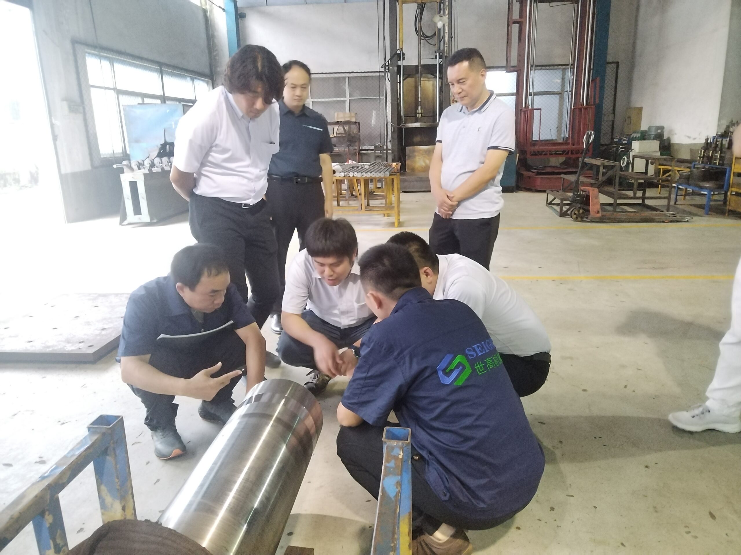
How SEIGO Handles Field-Measured Cylinder Specifications
SEIGO Machinery accepts field measurement specifications as the basis for aftermarket replacement cylinder quoting across all major OEM platforms. The workflow:
- Submit measured specifications via the contact form, with photos of the cylinder where possible
- Cross-reference against the SEIGO catalog of standard aftermarket replacement cylinders within one business day
- Receive either a confirmed catalog match (with OEM part number cross-reference) or a custom build quote with sealed mechanical drawing
- For custom builds, design review with engineering team to confirm specifications before production begins
- Standard 35–45 day production lead time with rapid-production track available
For aftermarket replacement work where the original OEM part number is unknown, unreadable, or not findable in any current parts catalog, the field measurement specification is the standard procurement path. Quality manufacturers welcome this approach — it’s how replacement cylinders for older equipment generations have always been sourced.
Material specifications on SEIGO field-spec replacement cylinders:
- Cylinder tube: 27SiMn alloy steel or 45# honed carbon steel
- Rod chrome thickness: ≥25 µm standard, ≥30 µm for mining
- Surface roughness: Ra ≤0.2 µm rod / Ra ≤0.4 µm tube
- Seal package: NOK (Japan) standard, with options for severe-duty service
- Pressure testing: 100% at 1.5× working pressure with individual test certificate
- Warranty: 12 months from shipment date
Ready to source a replacement cylinder from field measurements?
Send measured dimensions, machine details, and photos. SEIGO’s engineering team returns a confirmed cross-reference or custom build quote within one business day.
Submit Cylinder Specifications → Download the SEIGO Cylinder Catalog (PDF) →
SEIGO Machinery Equipment Co. is an ISO 9001-certified manufacturer of hydraulic cylinders for excavators, wheel loaders, dump trucks, drill rigs, mining equipment, and industrial applications. Thirty years of OEM-grade manufacturing experience, monthly capacity exceeding 6,000 units, and engineering CAD turnaround within one business day. Factory-direct pricing for global distributors and equipment fleets.
Note: Measurement procedures described should be performed on cylinders that are properly depressurized and supported. Hydraulic cylinders contain stored energy under pressure; disassembly without proper safety protocols can result in serious injury. Field measurement is one input to a complete replacement specification — consult with a qualified hydraulic cylinder supplier to verify cross-reference accuracy before committing to a purchase.
Related Reading:
- Hydraulic Cylinder Rod Damage: Chrome Scratches, Bending & Corrosion – Repair or Replace?
- Komatsu PC200/PC300 Hydraulic Cylinder Specs & Replacement Guide
- CAT Excavator Hydraulic Cylinder Replacement Guide: OEM vs Aftermarket Comparison
Related Categories: 未分类